This Procedure is intended to provide guidance and instructions for carrying out the
maintenance of DCS as per standard practices prescribed by OEM or General Industry best practices in
safe manner while ensuring minimization of Environmental impacts to the extent
possible.
DCS: Distributed control systems (DCSs) are computer-software packages communicating with control hardware and providing a centralized human–machine interface (HMI) for controlled equipment.
GENERAL RESPONSIBILITIES:
√ All the personnel involved in carrying out /supervising the above activities are required to ensure implementation of this procedure and may consult any other relevant documents indicated under Reference section below.
√ The event of
any changes required in the procedure such changes may be requested with
Station MR, who would take appropriate action with approval from respective
departmental head and Head –O&M.
OTHER GENERAL INSTRUCTIONS FOR COMPLIANCE:
√ Work permit as should be secured and instructions provided in the permit should be complied. Where instructions are not clear, clarification should be requested from the concerned Supervisior.Work should only be commenced after ensuring that proper work environment is created (ex: Authorizations are secured, Isolations are confirmed, and required mobilization is done.)
√ Access to Emergency evacuation and other emergency services such as medical and Fire protection shall be readily available and contact details are readily available concerned supervisor as well as contactor.
√ Access to drinking water, toilet and other essential infrastructure for both company and contract personnel should be ensured.
SAFETY PRECAUTION REQUIRED:
A. Use hand gloves while working with the system.
B. Ensure proper illumination.
C. Keep the fire extinguishers (CO2 cylinders) ready with reachable limit for any exigency.
D. Permit Type: Permit to Work Order
E. Permit Approving Authority: Shift in-charge (Main Control Room)
WORK INSTRUCTION
:
DCS system provide comprehensive process, monitoring, control function, display, alarming, calculation, data logging, data display, data storage etc. for BTG & its auxiliaries.
CONFIGURATION:
The configuration of DDC system is as per the project configuration diagram and the details of function grouping of TG & BOP systems are as per the Partitioning/Controller
Grouping document.
Fig-01: DCS Network Scheme
Procedure to Upload the Logic:
Download/Upload back file for DCS.
a. Click “All Program ----- max DNA -------max DNA Utilities ------------ max DPU Tools”
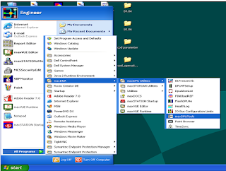
Fig 2: max DPU tool Navigation
b. Select Create a New Configuration.
Fig3: max DPU Tool Screen 01
Fig 4: max DPU Tool Screen 01
c. In DPU Selection, using the drop down menu select the DPU and save it in the location.
Procedure to Force a Tag:
A. Double click on Drive say CW Pump-01.
a. HTUD popup will open
b. Click on the icon. Near clear point.
Fig 05: max VUE Runtime screen
c. PT Details Tabular will open.
d. Click on text box, which tag need to force
.
e. Before the tag put “>” to force a tag as shown in fig-06.
Fig 08: final Screen after forcing the Tag.
Graphics Modification:
a. Click “start—max DNA—max VUE editor”
Fig 09: max VUE Editor Navigation
b. Click on .MN file & do the necessary modification
.
Fig 10: max VUE Editor Screen
Procedure to Add Tag in Historian:
a. Click “Start—max DNA—max Storian Utilities—MS Config”
Fig 11: MSConfig Navigation
b. Select .mdb file & click ok.
Fig 12: max STORIAN Configuration Editor Screen 01
c. Insert the tag/tags & click on to install added tags.
Fig 13: max STORIAN Configuration Editor Screen 02
Screen to be monitored on daily basis:
Fig 14: Network Status Screen
Fig 15: max STORIAN Status Screen
Fig 16: DPU 4F Status Screen
Fig 17: DPU 4F Pair Detail Status
NORMAL CHECKUP:
a. Clean all panel using vacuum cleaner. The vacuum cleaner must be kept at distance from the panel.
b. Check the input AC power supply. Check the tightness of all power cables.
c. Check the 24V dc power supply in the power module.
d. Tighten all the grounding cable in all the panel.
e. Ensure the Exhaust fan & light must be in running condition.
TRIAL / TEST PROCEDURE:
a. Take temporary clearance from MCR & make the power supply on in MCC end.
b. Ensure the proper supply voltage at the incoming end.
c. Switch On the MCB installed in processor Panel & check the electronic card healthiness
d. as mentioned above. If not ok, check for proper slot insertion/communication cable
e. Insertion/Chassis power supply etc.
f. If the problem still persists, replace the module.
g. Switch On the MCB installed in IO Panel & check the electronic card healthiness as
h. Mentioned above. If not ok, check for proper slot insertion/communication cable
i. Insertion /Chassis power supply etc. If the problem still persists, replace the module.
j. Check system healthiness/graphics in the OWS/EWS.
k. Close the all the panel door & remove all tools & manpower from the area.
l. Return the PTW.
CHECKS BEFORE RELEASE OF PERMIT
:
A. All T & P’s and manpower are removed.
B. Clean the maintenance area properly.
C. Return PTW & normalize all isolation after release of PTW.
HANDLING OF CONCESSIONS OR DEVIATIONS:
A. In the Event of Any Changes or Deviation from Procedure are required due to Urgent business requirements or system/Equipment approval should be obtained from Head O&M.
B. The report for the concerned task should clearly Captured the details of deviations and reason for the same.


Post a Comment